Description
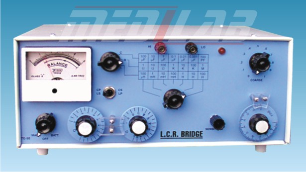
LCR Bridge (inductance, capacitance, and resistance) is a scientific instrument used to measure the inductance, capacitance, and resistance of electronic components. It works on the principle of comparing the unknown component with a known standard and then calculating its value based on the comparison.
The L.C.R. bridge typically consists of a source of alternating current (AC), a detector, and a null detector or galvanometer. The AC source is connected to the unknown component and a reference component, which is known and has a similar characteristic to the unknown component. The detector then measures the phase difference and amplitude of the AC signal between the two components. The null detector or galvanometer is used to indicate when the bridge is balanced, meaning that the phase difference and amplitude are the same for both components.
The L.C.R. bridge is used in various industries, including electronics, telecommunications, and manufacturing, to measure the inductance, capacitance, and resistance of components such as capacitors, inductors, and resistors. It is an essential tool in quality control processes, where it is used to ensure that electronic components meet the required specifications.
L.C.R. bridges are available in both analog and digital formats. Analog L.C.R. bridges use a galvanometer to indicate when the bridge is balanced, while digital L.C.R. bridges use digital signal processing (DSP) to display the results on a digital screen.


